
Normally my C8 rides on top of a Losmandy G11 which is great for astrophotography. But for those nights when I want to setup in the back yard for an hour or two of observing or those one-nighters out at the dark site, the G11 can be a bit too much to tear down and setup. What I really want is an SCT "grab and go" setup. I've been reading "The Dobsonian Telescope" by Kriege and Berry and have started thinking about building a big dob, something in the 18" range. But alas, discretionary spending is at a stand still at the ol' Barrett residence. So I thought, why not apply the concepts to build a portable mount for the SCT? What you see here are my feeble attempts to do just that.
The first problem to solve was cutting two perfect concentric circles to serve as the altitude bearings. Here is a simple circle cutting jig for the table saw. It is simply a 1/4" board with a nail driven at the appropriate radius. I cut a 3/8" by 3/4" strip of wood which is nailed to the underside with a few brads. This rides in the table groove. To use the jig, start with a more or less square piece of wood. Drill a 7/64" hole in the center. On the jig, drive an 8d finishing nail at the appropriate distance from the blade and cut off the head with a pair of wire cutters. This should be half the diameter of the circle you want to cut. Position your square at about a 45 degree angle. Slide the jig forward and back to cut off the corner. Twist the stock and cut off the other three corners sliding the jig forward and backward each time. Take care that you are only cutting wood. You will need all your fingers for the remainder of the project! Continue in this manner cutting the remaining angles until the only high spots are less than about a blade's width. Now slide the jig forward until it just starts to cut. Slowly spin the stock around. Slide the stock slightly forward again and slowly spin again. After about 3 iterations the blade cuts through the top of the stock all the way around and you are finished with a nice cleanly cut circle!

My C8 has Losmandy dovetails on top and bottom. These are used to attach the altitude bearings. Riding in this manner, the scope is essentially rotated 90 degrees from its "normal" position, but it's round so who cares? The altitude bearing is attached to the C8 with a couple strips of 3/16" hardwood cut at a 30 degree angle. This fits the Losmandy dovetail perfectly. Seen here the strips are attached with a couple of small pieces of double sided carpet tape to prove the concept. They are permanently attached with carpenter's glue and a few brads.
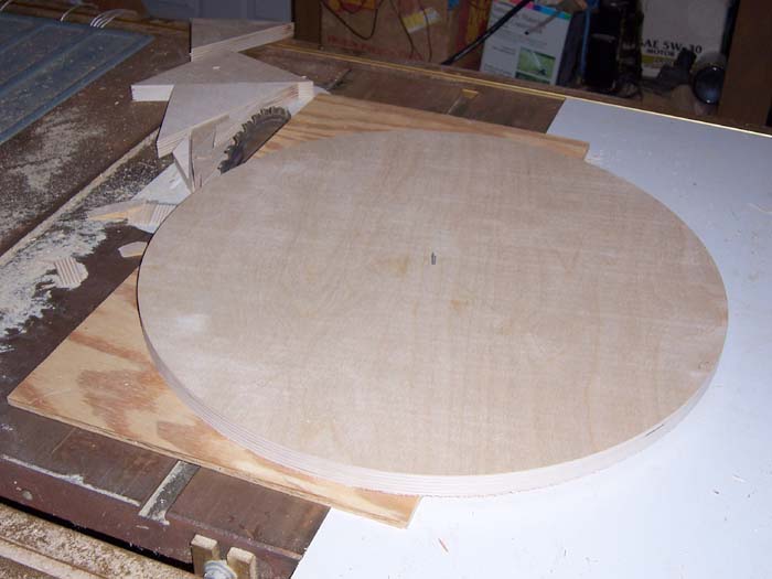
The ground board is 18 1/2". The circle cutting jig made this a piece of cake. The whole process took only about 10 minutes. This will be mounted on top of a surveyor's tripod and will carry the weight of the rocker box.

The tripod used is a CST Berger surveyor's tripod. This tripod is held together with 8mm bolts which are tapped into the top piece of aluminum. I discovered that I could remove these bolts and drill the holes through the top with a 1/4" bit. This allows me to mount the ground board with 1/4-20 bolts and nuts.

Here is the rocker box glued up and clamped. To allow room for my C8 SCT, the base is 13" by 13". The sides are 13" by 15". The back board is 11 1/2" by 8". These dimensions place the side boards about 1/4" wider than the altitude bearings when mounted on the scope. This allows a 1/8" clearance on either side to keep the bearings from rubbing the sides.

A Dobsonian purist would use Teflon pads on the ground board. Here I am using furniture glide strips. They work almost as well as Teflon for a fraction of the cost. You can find these at your hardware store sometimes sold with the name Magic Sliders or Super Sliders.

The base of the rocker box is covered in Formica. This surface riding on the furniture gliders is very smooth and buttery. A 1/2" hole is drilled in the center to attach the rocker box to the ground board.

The rocker box is attached to the ground board with a 1/2" bolt. This bolt is not tightened completely to allow movement around the azimuth axis.
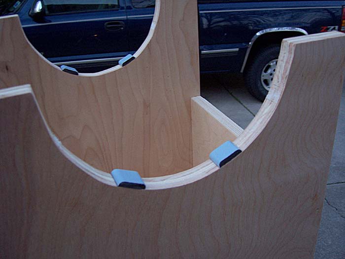
For the altitude bearings furniture glider pieces are used. Originally these were placed higher on the curve, but early field tests showed that this location resulted in too much stiction. Placing the pads lower cured the problem. Motion in the altitude axis is also smooth and buttery.

Here is the setup completely assembled. Since I used nice plywood I will probably just finish with a water resistant polyurethane to allow the wood grain to show through. The altitude bearings are also covered in Formica. A 1/4-20 bolt with a knob was threaded into the center of each altitude bearing as a clamp. I found that when the scope was pointed high in the sky the scope would tend to slide down in the bearings. By tightening the knobs down, sufficient pressure is placed on the dovetails to prevent slippage. When adding or removing accessories such as a dew shield the scope can be rebalanced easily by loosening the altitude clamps and shifting the scope fore or aft and re-clamping.
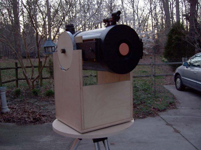
Here you can see why the front board is left short. There is ample room for those rare occasions when I'm somewhere where I have a negative horizon.

The sides were kept sufficiently high to allow pointing at the zenith. There is enough room in the box to allow the scope to be shifted down for rebalancing.
Initial field tests have been very encouraging. The mount moves very smoothly, but stays put where it is pointed (so long as it is properly balanced). Vibrations dampen well within a second.


